Have you ever wondered how those cool remote control cars work? It’s more than just batteries and a controller – it’s a fascinating blend of electronics and programming! For many, the world of electronics and coding might seem intimidating, shrouded in technical jargon and complex diagrams. However, building your own RC car and programming it to move is an incredibly rewarding and accessible project, even if you’re a complete beginner.
This guide will walk you through creating your very own Arduino-powered remote control car from the ground up. No prior experience with programming, Arduino, or electronics is needed. If you’ve ever dreamed of building your own gadgets or simply want to understand the magic behind RC vehicles, this project is for you. We’ll use readily available components and focus on clear, step-by-step instructions, making this project achievable for anyone. Plus, we’ll power our car using a power bank – a cost-effective and reusable power source that many of us already have! This tutorial will not only guide you through the build but also explain the underlying principles, giving you a solid foundation for future electronics and programming projects. Let’s dive in and bring your own programmable RC car to life!
Before we get started, gather these materials. You might be surprised at how affordable and accessible these components are:
- Arduino UNO: The brains of your RC car, easy to program and use.
- RC Car Chassis Kit: Includes the base, wheels, and motors – simplifies the mechanical build.
- Jumper Wires (Male-Male & Female-Male): For connecting components – makes wiring easier without soldering for beginners.
- Electrical Insulation Tape: For securing wires and ensuring safety.
- Bluetooth Module (HC-06 or HC-05): Enables wireless control from your Android phone.
- DC Motor Controller (L298N): Allows Arduino to control the speed and direction of the motors.
- Power Bank (with 2 USB Outputs): A convenient and rechargeable power source.
- Piezo Buzzer: For adding fun sound effects to your RC car.
- Android Mobile Phone: To control the car via Bluetooth.
- PC with Arduino IDE Installed: To program the Arduino board (free software).
- ArduCar – Arduino RC Car Bluetooth Controller App: A ready-made app to control your RC car (or explore alternatives!).
Step 1: Chassis Assembly
The first step is to assemble the physical base of our RC car – the chassis. Most chassis kits come with their own instructions, but here’s a general guide to get you started:
-
Prepare the Components: Lay out the chassis frame, motor mounting brackets (usually 4 small plastic pieces), screws, brass spacers, nuts, motors, a spare USB cable, and jumper wires.
-
Connect Wires to Motors: Each motor needs wires to connect to the motor controller. If you don’t have a soldering iron, you can carefully twist and secure jumper wires to each motor pin. For a more robust connection, soldering is recommended but not essential for this beginner project.
-
Prepare the USB Cable for Power: Take an old USB cable and cut off one end, leaving about 20cm (8 inches) of cable. Carefully strip a few centimeters of the outer cable covering to expose the inner wires. You’ll typically find 4 or 5 wires, but we only need the red (positive – VCC) and black (ground – GND) wires for power. Strip the red and black wire ends by 2-4cm. You can reinforce these connections by twisting them with longer jumper wires for a more secure connection.
-
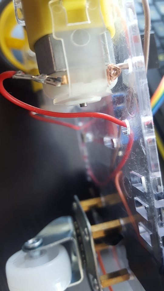
Mount Motors to Chassis: Attach the motors to the chassis frame using the plastic brackets, screws, and nuts. Most kits have designated spots for motor mounting. Note the small dot on one side of each motor; these dots should ideally face inwards towards each other when the motors are mounted on the chassis, ensuring consistent directionality.
-
Install the Supporting Wheel: Locate the square arrangement of four small holes at the rear of the chassis frame. Use brass spacers and screws to mount them in these holes. The spacers should be on the same side of the frame as the motors.
-
Attach the Nylon Supporting Wheel: Mount the nylon supporting wheel to the brass spacers using screws. This wheel provides stability to the rear of the car.
-
Mount the Wheels: Push the wheels onto the motor shafts. There’s usually a specific shape inside the wheel hub that aligns with the motor shaft. It might require a bit of force, but be gentle to avoid damaging the motor or wheel.
-
Mount Arduino and Motor Controller: Position the Arduino UNO board and the L298N DC motor controller on the chassis frame. Use screws and nuts (often included in the kit) to secure them. You can use electrical tape to insulate any exposed wires for safety.
Step 2: Wiring the Electronics
With the chassis assembled and components mounted, it’s time to connect everything electronically. This is where the magic happens, and your RC car starts to come to life! Have your jumper wires ready.
-
Connect Motors to Motor Controller: Take the wires from the motors and connect them to the L298N DC motor controller. The L298N has screw terminals labeled OUT1, OUT2, OUT3, and OUT4. Typically, the wiring is as follows:
- OUT1: Left Motor (-) GND wire
- OUT2: Left Motor (+) wire
- OUT3: Right Motor (+) wire
- OUT4: Right Motor (-) GND wire
Ensure you securely screw the wires into the terminals. Double-check the polarity (positive and negative) of your motors if you are unsure, though for basic functionality, getting it slightly wrong might just reverse the motor direction, which can be corrected in code or wiring later.
-
Connect Arduino to Motor Controller: Now we need to tell the motor controller what to do using the Arduino. We’ll use the L298N’s input pins (IN1, IN2, IN3, IN4) to send control signals from the Arduino. Use female-male jumper wires to connect:
- L298N IN1: Arduino Digital Pin 5
- L298N IN2: Arduino Digital Pin 6
- L298N IN3: Arduino Digital Pin 10
- L298N IN4: Arduino Digital Pin 11
These digital pins on the Arduino will send signals to the motor controller to control the direction and speed of each motor.
-
Connect Bluetooth Module: The Bluetooth module (HC-06 or HC-05) allows wireless communication between your Android phone and the Arduino. It has four pins: VCC, GND, TXD, and RXD. Connect them as follows:
- Bluetooth VCC: Arduino 5V Pin (Power)
- Bluetooth GND: Arduino GND Pin (Ground)
- Bluetooth TXD: Arduino Digital Pin 0 (RXD) – Note the cross-connection: TX to RX
- Bluetooth RXD: Arduino Digital Pin 1 (TXD) – Note the cross-connection: RX to TX
The TXD (Transmit Data) pin of the Bluetooth module connects to the RXD (Receive Data) pin of the Arduino, and vice versa. This is because one device’s transmit pin needs to talk to the other device’s receive pin for communication to occur.
-
Connect Piezo Buzzer (Optional): The piezo buzzer adds sound effects. It has two legs: a longer leg (Anode +) and a shorter leg (Cathode -). Connect them as follows:
- Piezo Buzzer Anode (+, longer leg): Arduino Digital Pin 3
- Piezo Buzzer Cathode (-, shorter leg): Arduino GND Pin (Ground)
While a 330 Ohm resistor is sometimes recommended for piezo buzzers to limit current, it’s often omitted in simple projects for louder sound. However, for long-term use or more sensitive buzzers, a resistor is advisable.
-
Powering the Motor Controller: Use the prepared USB cable (red and black wires) to power the L298N motor controller.
- USB Red Wire (+): L298N 12V Terminal (or similar voltage input, check your motor controller’s specs)
- USB Black Wire (-): L298N GND Terminal
-
Powering the Arduino: Connect another USB cable from your power bank to the Arduino UNO USB port. Connect the USB cable for the motor controller to the second USB output on your power bank.
-
Mount the Power Bank: Secure the power bank to the chassis using electrical tape or another mounting method. Ensure it’s stable and won’t interfere with the car’s movement.
With all the wiring complete, double-check every connection against the diagrams and instructions before proceeding to the programming stage.
Step 3: Programming Your RC Car
Now for the exciting part – programming your RC car’s brain! We’ll use the Arduino IDE to write and upload code to the Arduino board.
-
Install Arduino IDE: If you haven’t already, download and install the Arduino IDE from the official Arduino website (https://www.arduino.cc/en/software). Follow the installation instructions for your operating system.
-
Connect Arduino to PC: Connect your Arduino UNO board to your computer using a USB cable.
-
Select Board and Port: Open the Arduino IDE. Go to Tools > Board > Arduino UNO. Then, go to Tools > Port and select the COM port that corresponds to your Arduino. If you’re unsure, unplug and replug your Arduino; the new port that appears is likely the correct one.
-
Upload the Code: You have two options to get the code into your Arduino IDE:
a. Download and Open: Copy the code provided below and paste it into a new Arduino IDE window. Alternatively, you might be able to download a
.inofile if provided and open it directly in the Arduino IDE.b. Copy and Paste: Create a new sketch in the Arduino IDE (File > New) and copy and paste the following code into the editor window.
Important: Before uploading the code, disconnect the Bluetooth module’s TX and RX wires (connected to Arduino pins Digital 0 and 1). These pins are also used for USB communication during code upload, and leaving the Bluetooth module connected can interfere with the process.
#define in1 5 #define in2 6 #define in3 10 #define in4 11 int state; int piezo = 3; void setup() { pinMode(in1, OUTPUT); pinMode(in2, OUTPUT); pinMode(in3, OUTPUT); pinMode(in4, OUTPUT); pinMode(piezo,OUTPUT); Serial.begin(9600); } void loop() { if (Serial.available() > 0) { state = Serial.read(); Stop(); switch (state) { case 'F': forward(); soundFX(3000.0,30+400*(1+sin(millis()/5000))); break; case 'G': forwardleft(); soundFX(3000.0,60); break; case 'D': forwardright(); soundFX(3000.0,60); break; case 'N': backright(); soundFX(3000.0,30+100*(1+sin(millis()/2500))); break; case 'C': backleft(); soundFX(3000.0,30+100*(1+sin(millis()/2500))); soundFX(3000.0,30+100*(1+sin(millis()/2500))); soundFX(3000.0,30+100*(1+sin(millis()/2500))); soundFX(3000.0,30+100*(1+sin(millis()/2500))); break; case 'B': back(); soundFX(3000.0,30+200*(1+sin(millis()/2500))); soundFX(3000.0,30+200*(1+sin(millis()/2500))); soundFX(3000.0,30+200*(1+sin(millis()/2500))); soundFX(3000.0,30+200*(1+sin(millis()/2500))); break; case 'L': left(); soundFX(3000.0,60); soundFX(3000.0,60); soundFX(3000.0,60); soundFX(3000.0,60); break; case 'R': right(); soundFX(3000.0,60); soundFX(3000.0,60); soundFX(3000.0,60); soundFX(3000.0,60); break; case 'H': soundFX(3000.0,30+200*(1+sin(millis()/2500))); soundFX(3000.0,60); soundFX(3000.0,30+200*(1+sin(millis()/2500))); soundFX(3000.0,60); break; } } } void forward() { analogWrite(in1, 255); analogWrite(in3, 255); } void forwardleft() { analogWrite(in1, 50); analogWrite(in3, 255); } void forwardright() { analogWrite(in1, 255); analogWrite(in3, 50); } void back() { analogWrite(in2, 255); analogWrite(in4, 255); } void backright() { analogWrite(in2, 50); analogWrite(in4, 255); } void backleft() { analogWrite(in2, 50); analogWrite(in4, 50); } void left() { analogWrite(in4, 255); analogWrite(in1, 255); } void right() { analogWrite(in3, 255); analogWrite(in2, 255); } void Stop() { analogWrite(in1, 0); analogWrite(in2, 0); analogWrite(in3, 0); analogWrite(in4, 0); } void soundFX(float amplitude,float period){ int uDelay=2+amplitude+amplitude*sin(millis()/period); for(int i=0;i<200;i++){ digitalWrite(piezo, HIGH); delayMicroseconds(uDelay); digitalWrite(piezo, LOW); delayMicroseconds(uDelay); } } -
Upload the Sketch: Click the “Upload” button (the right arrow icon) in the Arduino IDE. The code will compile and upload to your Arduino board. You should see “Done uploading” in the status bar when it’s finished.
-
Reconnect Bluetooth Module: Once the code is uploaded, disconnect the USB cable from your computer, reconnect the Bluetooth module’s TX and RX wires to Arduino Digital 0 and 1, and connect the USB cable from the power bank to the Arduino to power it up.
-
Install and Use the Android App: Download the ArduCar – Arduino RC Car Bluetooth Controller app from the Google Play Store on your Android phone. Launch the app, connect to your Bluetooth module (you may need to pair with it in your phone’s Bluetooth settings first; default pairing code is often
1234or0000), and you should now be able to control your RC car wirelessly!
Step 4: Understanding the Arduino Code and Bluetooth (Optional)
For those eager to delve deeper, let’s break down the Arduino code and briefly touch on Bluetooth module configuration.
Arduino Code Explanation:
Every Arduino program has two main parts: setup() and loop().
-
void setup() { ... }: This section runs only once when the Arduino starts. Here, we configure the Arduino pins.pinMode(in1, OUTPUT);and similar lines set digital pins 5, 6, 10, 11 (namedin1,in2,in3,in4using#definefor clarity) asOUTPUTpins. This means the Arduino will send signals out of these pins to control the motor controller.pinMode(piezo, OUTPUT);sets digital pin 3 (namedpiezo) as an output for the piezo buzzer.Serial.begin(9600);initializes serial communication at a baud rate of 9600. This is how the Arduino communicates wirelessly with the Bluetooth module. 9600 baud is a common and reliable speed for Bluetooth communication.
-
void loop() { ... }: This section runs continuously in a loop, as long as the Arduino is powered.if (Serial.available() > 0) { ... }: This checks if there is any data available to read from the serial port (i.e., from the Bluetooth module).state = Serial.read();: If data is available, it reads the incoming character from the serial port and stores it in thestatevariable. This character is sent from your Android app when you press a control button.Stop();: Calls theStop()function to ensure the car stops before executing a new command.switch (state) { ... }: Thisswitchstatement checks the value of thestatevariable (the character received from Bluetooth) and executes different actions based on it.case 'F': forward(); soundFX(...); break;: Ifstateis ‘F’ (for “Forward”), it calls theforward()function to move the car forward and plays a sound effect usingsoundFX(). Similarcasestatements handle ‘G’ (Forward Left), ‘D’ (Forward Right), ‘B’ (Backward), ‘C’ (Backward Left), ‘N’ (Backward Right), ‘L’ (Left), ‘R’ (Right), and ‘H’ (Horn/Sound).break;: Thebreak;statement exits theswitchblock after acaseis executed.
-
Movement Functions (
forward(),back(),left(),right(),forwardleft(),forwardright(),backleft(),backright(),Stop()): These functions define how to control the motors to achieve different movements.analogWrite(in1, 255);:analogWrite()sends a PWM (Pulse Width Modulation) signal to a digital pin, effectively controlling the speed of the motor. Values from 0 (stopped) to 255 (full speed) are used. By controlling theanalogWrite()values to pins connected to the motor controller (in1, in2, in3, in4), we control the direction and speed of each motor, and thus the car’s movement. For example,forward()typically powers both forward motors at full speed (255).left()might power one side forward and the other backward to turn left.Stop()sets all motor control pins to 0, stopping the motors.
-
soundFX(float amplitude, float period): This function generates a simple sound effect using the piezo buzzer. It’s based on code found in Arduino forums for creating Sci-Fi sounds. It rapidly toggles the piezo pin HIGH and LOW at varying delays to produce different tones.
Bluetooth Module Configuration (Optional):
HC-05 and HC-06 Bluetooth modules come with default settings (like baud rate, name, and pairing PIN). While they often work out-of-the-box, you can configure them for advanced use. Configuration usually involves sending AT commands to the module via serial communication. You might want to change the Bluetooth module’s name, pairing PIN, or baud rate. This is an advanced topic, and numerous tutorials online explain how to configure Bluetooth modules using Arduino. Remember that Bluetooth modules often operate at 3.3V logic levels, while Arduino uses 5V. For robust communication, especially in configuration, level shifters or voltage dividers might be recommended to avoid potentially damaging the Bluetooth module, although often direct connection works for basic projects.
We hope this guide has illuminated the path to programming your own remote control car! Feel free to experiment with the code, add new features, and customize your RC car. Share your creations and any questions in the comments below – we’d love to see what you build!