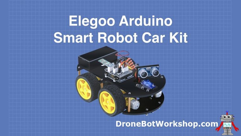
Getting started with robotics can be an exciting journey, and the Elegoo Smart Robot Car kit is an excellent platform for beginners and hobbyists alike. This guide will walk you through the initial steps of understanding and eventually programming your Elegoo Smart Robot Car. While assembling the car is the first step, the real magic happens when you bring it to life with code.
Many Arduino enthusiasts begin their robotics adventures by building a robot car. It’s a fantastic project that not only imparts valuable technical skills but also provides a tangible and impressive result. Robot car bases are readily available, simplifying the mechanical aspect. However, for newcomers, even with these bases, the process can seem complex, involving component mounting, wiring, and the ultimate challenge – programming.
The Elegoo Smart Robot Car kit offers a streamlined solution. It provides all necessary components in one package, ensuring compatibility and a higher chance of success. This article, the first in a series, will guide you through understanding your Elegoo Smart Robot Car and lay the groundwork for programming it to perform various tasks. We’ll start by exploring what makes this kit a great choice and then briefly touch upon assembly, before pivoting towards the exciting world of programming.
Discover the Elegoo Smart Robot Car
The Elegoo Smart Robot Car isn’t just a basic mobile platform; it’s packed with features designed to introduce you to a wide range of robotic concepts:
- Agile 4-Wheel Drive: Provides excellent maneuverability and control.
- Versatile Control Options: Includes IR Remote and Bluetooth control for immediate interaction.
- Intelligent Obstacle Avoidance: Equipped with Ultrasonic sensors to navigate autonomously.
- Line Following Capability: Sensors to follow defined paths, introducing line tracking concepts.
- Rechargeable Power: LiPo batteries and charger included for convenient and sustainable operation.
- Solder-Free Assembly: No soldering is required, making it accessible for beginners.
These features, combined with comprehensive instructions and readily available Arduino code examples, make the Elegoo Smart Robot Car an ideal learning tool for anyone eager to delve into Arduino programming and robotics.
Unboxing Your Elegoo Smart Robot Car Kit
The kit arrives in a robust orange case, perfect for storage and keeping components organized. Inside, you’ll find neatly arranged parts, and a helpful diagram on the lid interior identifies each component.
Here’s a breakdown of what you’ll find in your kit:
- Elegoo Arduino Uno R3 – The microcontroller brain of your robot.
- Chassis Base Plates (Top & Bottom) – Acrylic plates forming the car’s structure.
- DC Motors (x4) & Tires (x4) – For movement and traction.
- Custom Arduino Shield – Interface board simplifying connections and adding features like IR receiver.
- L298N Motor Controller – To drive the DC motors.
- 3-Channel Line Sensor Module – For line following functionality.
- SG90 Servo Motor – For rotating the ultrasonic sensor.
- HCSR04 Ultrasonic Distance Sensor – For obstacle detection.
- Bluetooth Module – For wireless control and communication.
- 18650 LiPo Batteries (x2) & Battery Holder – Power source for the car.
- Battery Charger – To recharge the batteries.
- Connection Cables – For connecting modules to the shield.
- USB Cable for Arduino – For programming and communication with your computer.
- IR Remote Control – For immediate remote operation.
- Mounting Brackets & Hardware – For assembling all the components.
- Screwdrivers & Hex Key – Tools included for assembly.
- Vinyl Electrical Tape – For cable management.
- CD ROM (Manuals & Code) – Software resources to get you started.
The labeled bags for hardware are a thoughtful touch, simplifying the assembly process significantly. With all these components at your disposal, you’re well-equipped to build and, more importantly, program a capable robot car.
Assembling the Smart Robot Car: A Quick Overview
While this article primarily focuses on programming, a functioning robot car is a prerequisite. The Elegoo kit provides excellent PDF instruction manuals, available on the included CD-ROM and for download from the Elegoo website. These manuals guide you step-by-step through the assembly.
For assembly, you’ll mainly need the included screwdrivers and hex key. Pliers can be helpful but aren’t essential. Elegoo’s clear instructions and labeled hardware bags make the physical build straightforward.
The assembly process involves several key stages:
Mounting Motors and Motor Mounts to the Chassis
This involves attaching aluminum mounting blocks to the DC motors and then securing them to the bottom chassis plate. Ensure motors are flush with the plate edge before tightening.
Installing the L298N Motor Driver
The L298N H-bridge driver, responsible for controlling the motors, is mounted onto the bottom chassis. Connect the motors to the L298N as shown in the manual.
Mounting the Line Follow Sensor
The line follow sensor array is mounted beneath the chassis, with the sensitivity potentiometer facing the front.
Attaching the Arduino Uno and Shield
The Arduino Uno is mounted on the top chassis plate, followed by the custom shield. Carefully align the pins when attaching the shield.
Installing the Battery Compartment
The battery compartment is mounted on the top plate. Ensure correct battery orientation when inserting the LiPo batteries.
Servo Motor and Ultrasonic Sensor Assembly
The servo motor is assembled with the ultrasonic sensor bracket and then mounted to the top chassis.
Finally, the ultrasonic sensor is mounted onto the servo, completing the sensor assembly.
Cable Connections and Final Assembly
Connect all cables to the Arduino shield as per the instructions, and then join the top and bottom chassis plates using spacers and screws. Attach the Bluetooth module and finally, mount the tires.
With assembly complete, your Elegoo Smart Robot Car is ready to be programmed!
Getting Started with Programming: Basic Movement
Now for the exciting part – making your robot car move! Elegoo provides sample code to get you started, which you can find on the CD-ROM or download from their website. The “lesson one” examples are perfect for initial testing.
Lesson one includes sketches like:
- forward_back.ino: Demonstrates forward and backward motion.
- left_wheel_rotation.ino & right_wheel_rotation.ino: Control individual wheels.
- speed_control.ino: Introduces motor speed control.
- AUTO_GO.ino: Moves the car in a sequence of directions.
Let’s examine the AUTO_GO.ino sketch to understand the basics of controlling your robot car’s movement. This sketch uses the L298N motor driver, which interfaces with the Arduino to control the DC motors.
Here’s the AUTO_GO.ino code for reference:
//www.elegoo.com
// The direction of the car's movement
// ENA ENB IN1 IN2 IN3 IN4 Description
// HIGH HIGH HIGH LOW LOW HIGH Car is runing forward
// HIGH HIGH LOW HIGH HIGH LOW Car is runing back
// HIGH HIGH LOW HIGH LOW HIGH Car is turning left
// HIGH HIGH HIGH LOW HIGH LOW Car is turning right
// HIGH HIGH LOW LOW LOW LOW Car is stoped
// HIGH HIGH HIGH HIGH HIGH HIGH Car is stoped
// LOW LOW N/A N/A N/A N/A Car is stoped

//define L298n module IO Pin
#define ENA 5
#define ENB 6
#define IN1 7
#define IN2 8
#define IN3 9
#define IN4 11

void forward(){
  digitalWrite(ENA,HIGH);//enable L298n A channel
  digitalWrite(ENB,HIGH);//enable L298n B channel
  digitalWrite(IN1,HIGH);//set IN1 hight level
  digitalWrite(IN2,LOW); //set IN2 low level
  digitalWrite(IN3,LOW); //set IN3 low level
  digitalWrite(IN4,HIGH);//set IN4 hight level
  Serial.println("Forward");//send message to serial monitor
}

void back(){
  digitalWrite(ENA,HIGH);
  digitalWrite(ENB,HIGH);
  digitalWrite(IN1,LOW);
  digitalWrite(IN2,HIGH);
  digitalWrite(IN3,HIGH);
  digitalWrite(IN4,LOW);
  Serial.println("Back");
}

void left(){
  digitalWrite(ENA,HIGH);
  digitalWrite(ENB,HIGH);
  digitalWrite(IN1,LOW);
  digitalWrite(IN2,HIGH);
  digitalWrite(IN3,LOW);
  digitalWrite(IN4,HIGH);
  Serial.println("Left");
}

void right(){
  digitalWrite(ENA,HIGH);
  digitalWrite(ENB,HIGH);
  digitalWrite(IN1,HIGH);
  digitalWrite(IN2,LOW);
  digitalWrite(IN3,HIGH);
  digitalWrite(IN3,HIGH); // Typo in original code, should be IN3, but logically IN3 LOW and IN4 HIGH for right turn
  digitalWrite(IN4,LOW);
  Serial.println("Right");
}

//before execute loop() function,
//setup() function will execute first and only execute once
void setup(){
  Serial.begin(9600);//open serial and set the baudrate
  pinMode(IN1,OUTPUT);//before useing io pin, pin mode must be set first
  pinMode(IN2,OUTPUT);
  pinMode(IN3,OUTPUT);
  pinMode(IN4,OUTPUT);
  pinMode(ENA,OUTPUT);
  pinMode(ENB,OUTPUT);
}

//Repeat execution
void loop(){
  forward(); //go forward
  delay(1000);//delay 1000 ms
  back(); //go back
  delay(1000);
  left(); //turning left
  delay(1000);
  right(); //turning right
  delay(1000);
}
To understand this code, you need to know how the L298N is connected to the Arduino:
- ENA (Enable A): Arduino Pin 5 (PWM – Speed control for motors A)
- ENB (Enable B): Arduino Pin 6 (PWM – Speed control for motors B)
- IN1 (Input 1): Arduino Pin 7 (Direction control for motor A)
- IN2 (Input 2): Arduino Pin 8 (Direction control for motor A)
- IN3 (Input 3): Arduino Pin 9 (Direction control for motor B)
- IN4 (Input 4): Arduino Pin 11 (Direction control for motor B)
The AUTO_GO.ino sketch defines these pin connections and sets them as outputs in the setup() function. It then defines functions for forward(), back(), left(), and right() movements by controlling the digital HIGH/LOW signals to the L298N, thus directing the motors. The loop() function calls these movement functions sequentially with delays, making the car move in a square pattern.
Important Note: Disconnect the Bluetooth module before uploading code to the Arduino, as it shares the serial communication lines with the USB port.
Basic Testing and Next Steps
To test your robot car, upload the AUTO_GO.ino sketch to your Arduino Uno using the Arduino IDE. Ensure you have selected the correct board and port in the IDE. Once uploaded, power on your robot car and observe its movement. It should move forward, backward, left, right, and repeat.
This basic test confirms that your motors, motor driver, and Arduino are correctly connected and functioning. It’s the first step in your programming journey!
In the subsequent parts of this series, we will delve deeper into programming your Elegoo Smart Robot Car. We’ll explore how to:
- Utilize Bluetooth and IR remote control for interactive operation.
- Program the line following capability to navigate tracks.
- Implement collision avoidance using the ultrasonic sensor for autonomous navigation.
Stay tuned for the next article, where we’ll unlock more advanced programming techniques to truly bring your Elegoo Smart Robot Car to life!
Parts List
Here are some components that you might need to complete the experiments in this article. Please note that some of these links may be affiliate links, and the DroneBot Workshop may receive a commission on your purchases. This does not increase the cost to you and is a method of supporting this ad-free website.
COMING SOON!
Resources
Elegoo Smart Robot Car – Official product page for the Elegoo Smart Robot Car.
Elegoo Robot Car Software – Download the latest instruction manual and sample code for the robot car.
Building the Elegoo Smart Robot Car Part 1 – Assemble an Arduino-Based Robot Car
Related
Summary
Article Name
Building the Elegoo Smart Robot Car Part 1 – Assemble an Arduino-Based Robot Car
Description
The Elegoo Smart Robot Car is an easy to assemble Arduino-based robot kit with several advanced features. In the first of a three-part article I will assemble the car and give it a quick test.
Author
DroneBot Workshop
Publisher Name
DroneBot Workshop
Publisher Logo
Tagged on: Arduino Project