Electronics and programming might seem daunting, especially if you’re more comfortable writing code than wiring circuits. Many believe that diving into electronics requires a degree in engineering. However, this couldn’t be further from the truth. For enthusiasts eager to blend the digital world with hands-on projects, Arduino offers an accessible entry point. If you, like many, harbored childhood dreams of building your own remote-controlled car, now is the perfect time to turn that dream into reality. With readily available Arduino kits and a bit of coding knowledge, creating your own Arduino-powered RC car is an achievable and incredibly rewarding project.
This guide will walk you through the process of building an Arduino-based RC car from scratch. Whether you’re a complete beginner with no prior experience in programming, Arduino, or electronics, or you have some background, this tutorial is designed to be easy to follow. We’ll use readily available and affordable components, focusing on a minimalistic approach to materials while providing a detailed explanation of the code. The principles you learn here can be applied to a wide range of other exciting DIY electronics projects. Let’s get started and bring your programmable RC car to life!
As a hobbyist, access to specialized tools isn’t always a given. This project cleverly utilizes common household electronic items like USB cables and power banks to minimize costs and maximize accessibility. Feel free to adapt and get creative with the materials, but here’s a list to get you started:
- Arduino UNO board
- RC car chassis kit (including wheels and DC motors)
- Male-male and female-male jumper wires
- Electrical insulation tape
- Bluetooth module (HC-06 or HC-05)
- L298N DC motor controller
- Power Bank (with at least 2 USB outputs)
- Piezo buzzer
- Android smartphone
- PC with Arduino IDE installed
- ArduCar – Arduino RC Car Bluetooth Controller App
Step 1: Assembling the RC Car Chassis
Let’s begin by putting together the foundation of our RC car – the chassis. If you purchased an RC car kit, it likely includes assembly instructions. However, we’ll outline the basic steps here to ensure everyone is on the same page:
-
Prepare the Components: Gather the main chassis frame, motor mounting brackets (usually four small plastic pieces, two for each motor), screws, brass spacers, nuts, DC motors, an old USB cable, and four jumper wires.
-
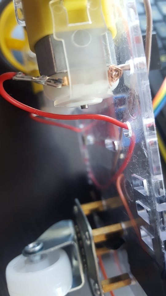
Connect Wires to Motors: Attach a jumper wire to each terminal of the DC motors. Soldering provides a robust connection, but for beginners or those without soldering equipment, securely twisting or “knotting” the wires to the motor pins will suffice.
-
Prepare the USB Cable for Power: Take an old USB cable and cut off one end, leaving approximately 20cm (8 inches) of cable length.
-
Expose Power Wires: Carefully strip a few centimeters of the outer insulation to reveal the internal wires. You should typically find 4 or 5 wires, but we are interested in only two: the ground (GND), which is usually black, and the power (VCC), typically red. Strip about 2-4 cm of insulation from the red and black wires. For a more secure connection, you can reinforce these by twisting or soldering them to longer, stronger jumper wires.
-
Mount Motors to Chassis: Attach the DC motors to the chassis frame using the plastic brackets, screws, and nuts. Most DC motors have a small dot on one side; ensure these dots face inwards towards each other when mounting the motors. This orientation is important for consistent motor direction.
-
Install Supporting Wheel: Locate the four small holes near the end of the chassis frame, usually arranged in a square. These are for the supporting nylon wheel. Use the brass spacers and screws to mount them in these holes. The spacers should be on the same side of the frame as the motors.
-
Attach Nylon Wheel: Secure the nylon supporting wheel to the brass spacers using screws. This wheel provides stability and balance to the RC car.
-
Mount Wheels to Motors: Push the wheels onto the motor shafts. You might encounter some resistance as the wheel hubs are designed for a snug fit. Apply gentle but firm pressure to ensure they are fully seated.
-
Mount Arduino and Motor Controller: Position the Arduino UNO board and L298N DC motor controller onto the chassis frame. Use screws and nuts from the kit or electrical tape to secure them in place. Ensure wires are neatly arranged and insulated with electrical tape where necessary to prevent shorts.
Step 2: Wiring the Arduino RC Car Electronics
With the chassis assembled and components mounted, it’s time to connect all the electronic parts. Prepare your male-male and female-male jumper wires.
-
Connect Motors to Motor Controller: Attach the wires from the motors to the L298N DC motor controller’s output terminals. The motor controller outputs are labeled OUT1, OUT2, OUT3, and OUT4. For wiring consistency, consider the pins closer to the edge of the board as ground (-) and the inner pins as positive (+). Connect them as follows:
- OUT1: Left motor (-) GND wire
- OUT2: Left motor (+) wire
- OUT3: Right motor (+) wire
- OUT4: Right motor (-) GND wire
-
Connect Arduino to Motor Controller: Now, we need to establish control signals from the Arduino to the motor controller. Use jumper wires to connect the Arduino’s digital pins to the L298N’s input pins (IN1, IN2, IN3, IN4). Female-male jumpers may be needed for direct connection. If unavailable, you can modify male-male jumpers or solder wires for a secure connection.
- IN1: Arduino Digital Pin 5
- IN2: Arduino Digital Pin 6
- IN3: Arduino Digital Pin 10
- IN4: Arduino Digital Pin 11
-
Connect Bluetooth Module: The Bluetooth module enables wireless control of your RC car. HC-06 or HC-05 modules typically have four pins: VCC (Power), GND (Ground), TXD (Transmit Data), and RXD (Receive Data). Use female-male jumper wires to connect them to the Arduino:
- VCC: Arduino 5V pin
- GND: Arduino GND pin
- TXD: Arduino Digital Pin 0 (RXD) – Note the cross-wiring: Bluetooth TX to Arduino RX
- RXD: Arduino Digital Pin 1 (TXD) – Note the cross-wiring: Bluetooth RX to Arduino TX
Data transmission requires cross-wiring – the transmitter (TX) of one device connects to the receiver (RX) of the other, and vice versa.
-
Connect Piezo Buzzer: A piezo buzzer adds auditory feedback to your RC car. It has two pins: a longer anode (+) and a shorter cathode (-). While a 330 Ohm resistor is often recommended in series with the anode to limit current and sound volume, it can be omitted for a louder sound if desired. Connect as follows:
- Anode (+) (Longer leg): Arduino Digital Pin 3
- Cathode (-) (Shorter leg): Arduino GND pin
-
Powering the Motor Controller: Use the prepared USB cable from Step 1. Connect the red wire (+) and black wire (-) to the L298N motor controller’s power input terminals. These are typically labeled 12V and GND.
- Red wire (+): L298N 12V input
- Black wire (-): L298N GND input
-
Powering the Circuit: Finally, connect two USB cables to your power bank. One cable will power the Arduino board, and the other will power the DC motor controller via the USB cable connected in the previous step. Mount the power bank securely to the chassis using electrical tape or another mounting method. Some power banks have a power button that needs to be switched on to activate the outputs.
-
Code and Control: With all components wired, the next step is to program the Arduino and install a control application on your smartphone.
Step 3: Programming Your Arduino RC Car
Now for the exciting part – programming your Arduino RC car to respond to your commands! You’ll need the Arduino IDE (Integrated Development Environment) installed on your computer, which you can download from the official Arduino website.
-
Setting up Arduino IDE:
- Open the Arduino IDE.
- Go to “Tools” > “Board:” and select “Arduino Uno” (or your specific Arduino board).
- Then, go to “Tools” > “Port:” and choose the port that your Arduino is connected to. If you don’t see a port listed, ensure your Arduino is connected to your computer via USB. You might need to try different USB ports on your computer until the Arduino is recognized.
-
Uploading the Arduino Code: You have two ways to get the code onto your Arduino:
- Option 1: Download and Open: Download the provided Arduino code file (if available). Open the file in the Arduino IDE and proceed to upload.
- Option 2: Copy and Paste: Create a new sketch in the Arduino IDE (File > New). Copy the code provided below and paste it into the new sketch.
Click the “Upload” button (usually a right arrow) in the Arduino IDE to compile and upload the code to your Arduino board.
Important Note: Disconnect the Bluetooth module’s TX and RX pins (Digital 0 and 1) from the Arduino before uploading the code. These pins are used for serial communication, and having the Bluetooth module connected during upload can interfere with the process, causing the upload to fail or freeze. Reconnect them after the code is uploaded.
Here’s the Arduino code you’ll need:
#define in1 5 #define in2 6 #define in3 10 #define in4 11 int state; int piezo = 3; void setup() { pinMode(in1, OUTPUT); pinMode(in2, OUTPUT); pinMode(in3, OUTPUT); pinMode(in4, OUTPUT); pinMode(piezo,OUTPUT); Serial.begin(9600); } void loop() { if (Serial.available() > 0) { state = Serial.read(); Stop(); switch (state) { case 'F': forward(); soundFX(3000.0,30+400*(1+sin(millis()/5000))); break; case 'G': forwardleft(); soundFX(3000.0,60); break; case 'D': forwardright(); soundFX(3000.0,60); break; case 'N': backright(); soundFX(3000.0,30+100*(1+sin(millis()/2500))); break; case 'C': backleft(); soundFX(3000.0,30+100*(1+sin(millis()/2500))); soundFX(3000.0,30+100*(1+sin(millis()/2500))); soundFX(3000.0,30+100*(1+sin(millis()/2500))); soundFX(3000.0,30+100*(1+sin(millis()/2500))); break; case 'B': back(); soundFX(3000.0,30+200*(1+sin(millis()/2500))); soundFX(3000.0,30+200*(1+sin(millis()/2500))); soundFX(3000.0,30+200*(1+sin(millis()/2500))); soundFX(3000.0,30+200*(1+sin(millis()/2500))); break; case 'L': left(); soundFX(3000.0,60); soundFX(3000.0,60); soundFX(3000.0,60); soundFX(3000.0,60); break; case 'R': right(); soundFX(3000.0,60); soundFX(3000.0,60); soundFX(3000.0,60); soundFX(3000.0,60); break; case 'H': soundFX(3000.0,30+200*(1+sin(millis()/2500))); soundFX(3000.0,60); soundFX(3000.0,30+200*(1+sin(millis()/2500))); soundFX(3000.0,60); break; } } } void forward() { analogWrite(in1, 255); analogWrite(in3, 255); } void forwardleft() { analogWrite(in1, 50); analogWrite(in3, 255); } void forwardright() { analogWrite(in1, 255); analogWrite(in3, 50); } void back() { analogWrite(in2, 255); analogWrite(in4, 255); } void backright() { analogWrite(in2, 50); analogWrite(in4, 255); } void backleft() { analogWrite(in2, 255); analogWrite(in4, 50); } void left() { analogWrite(in4, 255); analogWrite(in1, 255); } void right() { analogWrite(in3, 255); analogWrite(in2, 255); } void Stop() { analogWrite(in1, 0); analogWrite(in2, 0); analogWrite(in3, 0); analogWrite(in4, 0); } void soundFX(float amplitude,float period){ int uDelay=2+amplitude+amplitude*sin(millis()/period); for(int i=0;i<200;i++){ digitalWrite(piezo, HIGH); delayMicroseconds(uDelay); digitalWrite(piezo, LOW); delayMicroseconds(uDelay); } } -
Reconnect and Power Up: After successful code upload, reconnect the Bluetooth module’s TX and RX pins to Arduino Digital pins 0 and 1. Reconnect the USB power cables (Arduino to power bank, and motor controller to power bank).
-
Install and Use the Control App: To control your RC car, download the “ArduCar – Arduino RC Car Bluetooth Controller” app from the Google Play Store. Launch the app, connect to your Bluetooth module, and start driving!
Alternatively, you can use other Bluetooth serial controller apps that send matching serial commands or even develop your own custom mobile application for enhanced control.
Congratulations! You’ve successfully built and programmed your own Arduino RC car. Enjoy driving and experimenting with your creation! For any questions or further ideas, feel free to leave comments below.
Step 4: Understanding the Arduino Code for Your RC Car
For those eager to delve deeper into the code that powers your RC car, let’s break down the Arduino sketch. This explanation will help you understand the logic and mechanics, empowering you to customize and expand your project.
Arduino code is written in a simplified C/C++-like language, making it relatively accessible even for beginners. The code is structured into key sections:
-
void setup() { }: This section runs only once when the Arduino starts. It’s used to initialize settings, such as configuring pin modes.In our code:
void setup() {
  pinMode(in1, OUTPUT);
  pinMode(in2, OUTPUT);
  pinMode(in3, OUTPUT);
  pinMode(in4, OUTPUT);
  pinMode(piezo,OUTPUT);
  Serial.begin(9600);
}
pinMode(pin, OUTPUT);: This line sets the specified pin (in1,in2,in3,in4,piezo) as anOUTPUTpin. This means the Arduino will send signals out from these pins to control other components (like the motor controller and buzzer). If it were set toINPUT, the Arduino would receive signals, typically from sensors.Serial.begin(9600);: This initializes serial communication at a baud rate of 9600 bits per second. Serial communication is used here for the Arduino to communicate wirelessly with the Bluetooth module. The baud rate must match the Bluetooth module’s setting for successful data exchange. 9600 is a common and stable baud rate.
-
void loop() { }: This is the main part of the program, which runs continuously aftersetup()completes. It contains the code that controls the RC car’s behavior in response to commands.void loop() { if (Serial.available() > 0) { state = Serial.read(); Stop(); switch (state) { // ... cases for different commands ... } } }if (Serial.available() > 0): This checks if there is any data available to be read from the serial port (i.e., from the Bluetooth module).Serial.available()returns the number of bytes of data waiting to be read. If it’s greater than 0, it means a command has been received.state = Serial.read();: This reads the first byte of incoming serial data and stores it in thestatevariable. This byte represents the command sent from the control app (e.g., ‘F’ for forward, ‘L’ for left).Stop();: This function (defined later in the code) immediately stops the car’s motors, ensuring it doesn’t continue moving from a previous command.switch (state) { ... }: Thisswitchstatement checks the value of thestatevariable and executes different actions based on the received command. Eachcasecorresponds to a specific command character.
-
Pin and Variable Definitions: Before
setup(), we define names for the Arduino pins we’re using and declare variables:#define in1 5 #define in2 6 #define in3 10 #define in4 11 int state; int piezo = 3;#define in1 5: This is a preprocessor directive that definesin1as a symbolic name for digital pin 5. Wheneverin1is used in the code, the Arduino IDE replaces it with the number 5. This makes the code more readable and easier to modify. Similar definitions are made forin2,in3, andin4, corresponding to the input pins of the motor controller, andpiezofor the piezo buzzer pin (Digital pin 3).int state;: This declares an integer variable namedstate. This variable will store the command character received from the Bluetooth module.int piezo = 3;: This declares an integer variable namedpiezoand initializes it with the value 3, representing the Arduino pin connected to the piezo buzzer.
-
Motor Control Functions: The code includes functions to control the car’s movement:
forward(),back(),left(),right(),forwardleft(),forwardright(),backleft(),backright(), andStop().Example:
void forward() {
  analogWrite(in1, 255);
  analogWrite(in3, 255);
}
void forward() { ... }: This defines a function namedforward. When called, it makes the car move forward.analogWrite(pin, value);: This function is used to control the speed of the motors. It sends a PWM (Pulse Width Modulation) signal to the specified pin. Thevalueranges from 0 to 255, where 0 is off (0% speed) and 255 is full speed (100% speed). Inforward(),analogWrite(in1, 255);andanalogWrite(in3, 255);set both left and right motors to full speed in the forward direction (by activatingin1andin3pins of the motor controller). The specific pins (in1,in2,in3,in4) and their combinations determine the direction of motor rotation and thus the car’s movement.
-
Sound Effects Function: The
soundFX()function controls the piezo buzzer to generate simple sounds.void soundFX(float amplitude,float period){ int uDelay=2+amplitude+amplitude*sin(millis()/period); for(int i=0;i<200;i++){ digitalWrite(piezo, HIGH); delayMicroseconds(uDelay); digitalWrite(piezo, LOW); delayMicroseconds(uDelay); } }void soundFX(float amplitude, float period) { ... }: This function takesamplitudeandperiodas parameters to control the sound.digitalWrite(piezo, HIGH);anddigitalWrite(piezo, LOW);: These lines rapidly turn the piezo buzzer pin on and off to generate sound waves. ThedelayMicroseconds(uDelay);function controls the duration of the HIGH and LOW states, affecting the frequency and tone of the sound. The formula foruDelayand the loop create a varying tone, making a simple sound effect.
This detailed code explanation should give you a solid understanding of how your Arduino RC car is programmed. Feel free to experiment with the code, modify speeds, add new sound effects, or even integrate sensors for more advanced functionalities. Happy coding and driving!