Have you ever looked at a toy car and wished you could do more than just push it around? What if you could build your own remote control, and program it to make your toy car move exactly as you want? For many, the world of electronics and programming seems daunting, filled with complex circuits and lines of code. But the truth is, getting started with electronics and programming, especially for fun projects like controlling a toy car with a custom remote, is more accessible than you might think. If you’ve ever dreamt of creating your own remote-controlled toy car, this guide is for you.
This tutorial will walk you through the exciting process of building and programming your own Arduino-based remote control for a toy car. You don’t need to be an electronics whiz or a coding expert to follow along. Whether you’re a complete beginner or have dabbled in coding before, this project is designed to be easy to understand and incredibly rewarding. We’ll break down each step, from assembling the car chassis to writing the code that brings your remote control to life. We’ll use readily available components, focusing on simplicity and affordability, even making use of everyday items like a power bank. By the end of this guide, you’ll not only understand How To Program A Remote To A Toy Car, but also grasp fundamental principles that can be applied to countless other exciting projects. Let’s bring your childhood dreams to reality and get started!
Before we dive in, it’s worth noting that this guide is inspired by a previous project focused on Arduino-controlled RC cars. Consider this an enhanced and more detailed version, specifically tailored to help you understand the process of programming the remote control aspect. While we will be using Arduino and Bluetooth for wireless control, the core principles of controlling motors and responding to remote inputs are universally applicable. Let’s have some fun and build something amazing!
Step 1: Gathering Your Materials and Assembling the Chassis
The first step in our journey to program a remote to control a toy car is to gather all the necessary components. We’re aiming for a project that’s accessible and doesn’t require specialized tools. For many hobbyists starting out, expensive equipment can be a barrier. That’s why we’ll focus on using affordable and commonly available items, even repurposing old electronics you might have around your house. Here’s a list of everything you’ll need to get started:
- Arduino UNO: This is the brain of our operation. Arduino UNO is a popular microcontroller board that’s easy to program and perfect for beginners.
- Toy Car Chassis Kit with Wheels and Motors: You can find these kits online. Look for a kit that includes a basic chassis, wheels, and DC motors. Having a kit simplifies the mechanical assembly process significantly.
- Jumper Wires (Male-Male and Female-Male): These wires will be our electrical connectors, allowing us to link all the components together. Having both types will give you flexibility in your connections.
- Electrical Insulation Tape: Essential for securing connections and preventing short circuits.
- Bluetooth Module (HC-06 or HC-05): This module will enable wireless communication between your remote control (Android phone) and the toy car. Both HC-06 and HC-05 are suitable; HC-05 is slightly more versatile if you plan on more complex Bluetooth projects later.
- DC Motor Controller (L298N): The motor controller is crucial for driving the DC motors of the car. Arduino alone cannot directly power the motors; the L298N acts as an intermediary, handling the higher current needed for the motors.
- Power Bank with 2 USB Outputs: Power banks are a convenient and rechargeable power source. Using one with two outputs allows us to power both the Arduino and the motor controller separately if needed.
- Piezo Buzzer: This is optional but adds a fun element. We can program the buzzer to make sounds when the car moves, adding an extra layer of feedback and enjoyment.
- Android Mobile Phone: We’ll use an Android phone as our remote control, utilizing a readily available Bluetooth control app.
- PC with Arduino IDE Installed: You’ll need a computer to write and upload the code to your Arduino. Arduino IDE is free software that you can download from the official Arduino website.
- USB Cable (Spare): We’ll repurpose a USB cable to get power wires for the motor controller, showcasing how to use what you have on hand.
- ArduCar – Arduino RC Car Bluetooth Controller App (or similar): This Android app, or others like it, will serve as our remote control interface.
Once you have all the materials, the first physical step is to assemble the chassis of your toy car. If you purchased a kit, it likely comes with its own assembly instructions. However, if you’re working with a more generic chassis, here’s a general guideline:
-
Prepare the Motor Mounts: Most chassis kits will include plastic brackets designed to hold the DC motors in place. Gather these brackets, along with screws, brass spacers, and nuts. Identify the parts that will be used to mount the motors to the chassis frame.
-
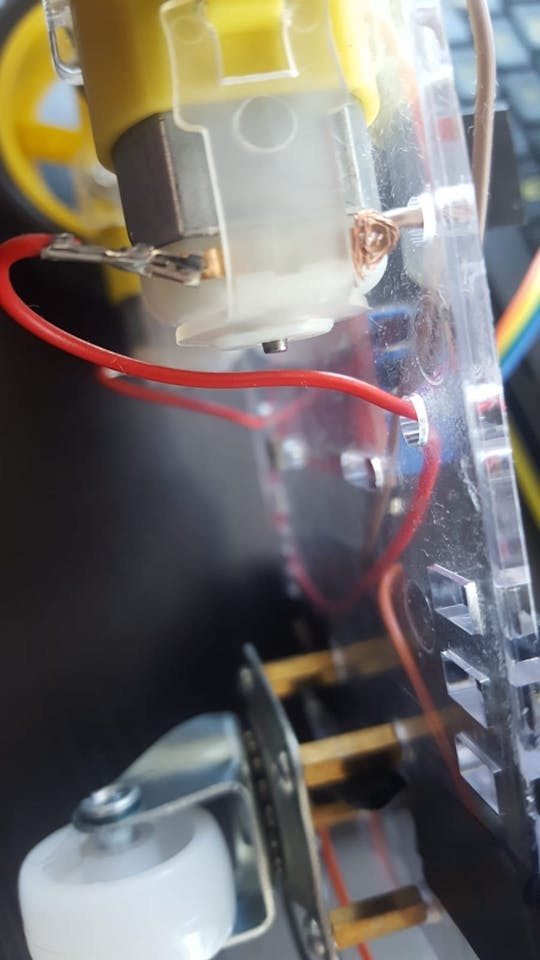
Connect Wires to Motors: Before mounting the motors, it’s easier to connect the wires. Each DC motor will have two pins. Take four jumper wires (or short lengths of regular wire) and connect one wire to each pin of both motors. Soldering is ideal for a robust connection, but if you don’t have a soldering iron, you can securely twist the wires around the motor pins to ensure good contact.
Alt Text: DC motor with jumper wires securely connected to the terminals, ready for mounting onto the toy car chassis. -
Prepare the USB Power Cable: Take your spare USB cable. We’re going to cut off one end (the end that usually plugs into your phone) leaving about 20cm (8 inches) of cable with the USB-A connector intact. Carefully strip a few centimeters of the outer insulation to reveal the internal wires. You should find several wires inside, but we’re primarily interested in the red (positive/VCC) and black (ground/GND) wires. Strip about 2-4 cm of insulation from the red and black wires. You can either use these bare wires or, for a more durable connection, twist or solder them to longer jumper wires. This USB cable will be used to power the motor controller from the power bank.
Image: Stripped USB cable showing red and black power wires exposed, prepared for connection to the motor controller.
Alt Text: Close-up of a modified USB cable with insulation stripped to expose the red and black power wires for use in powering the toy car’s motor controller. -
Mount the Motors to the Chassis: Now, attach the motors to the chassis frame using the plastic brackets, screws, and nuts from your kit. Pay attention to the orientation of the motors. Many kits suggest that a small “dot” or marker on the motor should face inwards towards the center of the chassis when both motors are mounted. This ensures consistent directionality for both wheels.
Alt Text: Toy car chassis with DC motors mounted and secured with plastic brackets, screws, and nuts, ready for wheel installation. -
Install the Supporting Wheel: Most toy car chassis kits include a third, smaller nylon wheel that acts as a support, usually at the rear of the car. Locate the set of four small holes near the end of the chassis frame, often arranged in a square. Use brass spacers and screws to mount the spacers to these holes, positioning them on the same side of the frame as the motors. Then, attach the nylon supporting wheel to the brass spacers using screws.
Alt Text: Toy car chassis with the rear nylon supporting wheel installed using brass spacers and screws for stability. -
Attach the Wheels to the Motors: Now it’s time to put the wheels onto the motor shafts. Examine the wheel hubs; you’ll notice a specific shape inside that needs to align with the motor shaft. Push the wheels onto the shafts. It might require a bit of force, but be gentle and ensure they are firmly in place.
-
Mount Arduino and Motor Controller: With the wheels on, you can now mount the Arduino UNO board and the L298N DC motor controller onto the chassis frame. Many kits provide mounting holes or spaces for these components. Use screws and nuts from the kit to secure them to the frame. If needed, use electrical tape to insulate any exposed wires or connections for safety and neatness.
Alt Text: Toy car chassis with Arduino UNO and L298N DC motor controller securely mounted and positioned for wiring in the next step.
With the chassis assembled and the main electronic components mounted, we’re ready to move on to the next critical step: wiring everything together.
Step 2: Wiring the Electronics – Connecting the Remote Control Brain
Now that the physical assembly of our toy car is complete, it’s time to connect all the electronic components. This step is crucial for enabling remote control. We’ll be using jumper wires to create the connections between the Arduino, motor controller, Bluetooth module, and buzzer. Let’s proceed step-by-step to ensure everything is wired correctly:
-
Connect Motors to the DC Motor Controller: Take the wires you previously connected to the motors and connect them to the L298N DC motor controller. The L298N has screw terminals for motor connections labeled OUT1, OUT2, OUT3, and OUT4. For each motor, you’ll connect one wire to an OUT terminal and the other to its corresponding adjacent OUT terminal. Let’s define the connections as follows, keeping in mind motor polarity might need adjustment later if the car moves in the opposite direction initially:
- OUT1: Left Motor (-) (Typically Ground wire, often black)
- OUT2: Left Motor (+) (Power wire, color may vary)
- OUT3: Right Motor (+) (Power wire, color may vary)
- OUT4: Right Motor (-) (Typically Ground wire, often black)
Loosen the screws on the terminal blocks, insert the wire ends, and tighten the screws to secure the connections. Ensure the wires are firmly held.
Alt Text: L298N DC motor controller showing motor wires connected to OUT1, OUT2, OUT3, and OUT4 terminals, securing the power to the car’s drive motors. -
Connect Arduino to the DC Motor Controller (Control Signals): Now we need to connect the Arduino to the motor controller so that Arduino can send commands to control the motors. We’ll use the control input pins on the L298N, labeled IN1, IN2, IN3, and IN4. These pins will receive signals from the Arduino to control the direction and speed of the motors. Use female-male jumper wires to connect these pins to the digital pins on the Arduino as follows:
- L298N IN1 to Arduino Digital Pin 5
- L298N IN2 to Arduino Digital Pin 6
- L298N IN3 to Arduino Digital Pin 10
- L298N IN4 to Arduino Digital Pin 11
Carefully plug the female ends of the jumper wires onto the L298N pins and the male ends into the corresponding digital pins on the Arduino.
-
Connect the Bluetooth Module: The Bluetooth module is our wireless communication link, allowing us to control the car from our Android phone. The Bluetooth module (HC-06 or HC-05) typically has four pins: VCC, GND, TXD, and RXD. Use female-male jumper wires to connect these pins to the Arduino:
- Bluetooth VCC to Arduino 5V Pin (Power)
- Bluetooth GND to Arduino GND Pin (Ground)
- Bluetooth TXD to Arduino Digital Pin 0 (RX) (Transmit Data – Bluetooth transmits to Arduino’s receiver)
- Bluetooth RXD to Arduino Digital Pin 1 (TX) (Receive Data – Bluetooth receives from Arduino’s transmitter)
Note the cross-wiring of TX and RX. The transmit pin of one device needs to connect to the receive pin of the other for data communication.
Alt Text: HC-06 Bluetooth module connected to Arduino UNO with jumper wires, linking VCC, GND, TXD, and RXD pins for wireless communication control. -
Connect the Piezo Buzzer (Optional): If you’re adding a piezo buzzer for sound effects, it has two legs: a longer leg (Anode, +) and a shorter leg (Cathode, -). Connect them as follows:
- Piezo Buzzer Anode (Longer Leg) to Arduino Digital Pin 3
- Piezo Buzzer Cathode (Shorter Leg) to Arduino GND Pin
While it’s often recommended to use a 330 Ohm resistor in series with the piezo buzzer to limit current, it’s optional for basic sound effects and may reduce the volume. For simplicity, we’ll omit the resistor in this basic setup, but be mindful that prolonged use without a resistor could potentially shorten the buzzer’s lifespan.
Image: Piezo buzzer connected to Arduino UNO using jumper wires, showing anode and cathode connections.
Alt Text: Piezo buzzer wired to Arduino UNO with jumper wires, illustrating the connection of the longer anode leg to digital pin 3 and the shorter cathode leg to ground. -
Powering the Motor Controller: Remember the modified USB cable? We’ll use this to power the L298N motor controller. Connect the stripped red and black wires as follows to the L298N screw terminals:
- Red Wire (+) to L298N 12V Terminal (Voltage input for motors)
- Black Wire (-) to L298N GND Terminal (Ground)
Securely tighten the screws on the terminal block to hold the wires in place.
-
Powering the Arduino and Final Power Setup: Finally, we need to power the Arduino itself. You can power the Arduino and the motor controller using the power bank. Use two separate USB cables.
- USB Cable 1: Plug one end into a USB port on your power bank and the other end into the USB port on the Arduino UNO.
- USB Cable 2 (Modified): Plug the USB-A connector of your modified USB cable into a second USB port on the power bank. The other end is already connected to the L298N motor controller’s power terminals.
Mount the power bank onto the chassis frame using electrical tape or another secure method. Ensure it’s stable and won’t interfere with the car’s movement. Some power banks have a power button; make sure to turn it on to supply power to the circuit.
Alt Text: Electrical circuit diagram illustrating the complete wiring connections between the Arduino UNO, L298N motor controller, HC-06 Bluetooth module, piezo buzzer, and power bank for the DIY toy car project.
With all the wiring complete, double-check each connection to ensure they are secure and in the correct locations. Now we’re ready for the exciting part: programming the remote control!
Step 3: Programming Your Remote Control – Bringing Code to Life
With the hardware assembled and wired, the next crucial step is to program the Arduino to understand remote control commands. This is where we bridge the gap between electronics and software, teaching the Arduino how to interpret signals from our Bluetooth remote and translate them into actions for the toy car motors. We’ll use the Arduino IDE to write and upload code to the Arduino board.
-
Install and Setup Arduino IDE: If you haven’t already, download and install the Arduino IDE (Integrated Development Environment) from the official Arduino website (https://www.arduino.cc/). Once installed, open the Arduino IDE.
-
Select Board and Port: Connect your Arduino UNO board to your computer using a USB cable. In the Arduino IDE, go to Tools > Board and select Arduino Uno. Then, go to Tools > Port and choose the serial port that corresponds to your Arduino. The port number may vary depending on your operating system and other connected devices. If you’re unsure, disconnect and reconnect your Arduino and see which port disappears and reappears in the list.
Alt Text: Arduino IDE interface screenshot demonstrating how to select the correct board (Arduino Uno) and serial port from the Tools menu for programming the microcontroller. -
Upload the Code: You have two options to get the code into the Arduino IDE:
- Option 1: Download and Open Code File: You can download the complete Arduino code provided below (or from the original source if available as a file). Open the downloaded file directly in the Arduino IDE.
- Option 2: Copy and Paste Code: Alternatively, you can create a new sketch in the Arduino IDE (File > New) and copy and paste the code provided below into the sketch window.
Important Note: Before uploading the code, disconnect the jumper wires connected to Arduino Digital Pin 0 (RX) and Digital Pin 1 (TX) of the Bluetooth module. These pins are used for serial communication during code upload, and interference from the Bluetooth module can prevent successful uploading.
Here is the Arduino code that you will upload:
#define in1 5
#define in2 6
#define in3 10
#define in4 11
int state;
int piezo = 3;

void setup() {
  pinMode(in1, OUTPUT);
  pinMode(in2, OUTPUT);
  pinMode(in3, OUTPUT);
  pinMode(in4, OUTPUT);
  pinMode(piezo,OUTPUT);
  Serial.begin(9600);
}

void loop() {
  if (Serial.available() > 0) {
    state = Serial.read();
    Stop();
    switch (state) {
      case 'F': forward(); soundFX(3000.0,30+400*(1+sin(millis()/5000))); break;
      case 'G': forwardleft(); soundFX(3000.0,60); break;
      case 'D': forwardright(); soundFX(3000.0,60); break;
      case 'N': backright(); soundFX(3000.0,30+100*(1+sin(millis()/2500))); break;
      case 'C': backleft(); soundFX(3000.0,30+100*(1+sin(millis()/2500)));
                 soundFX(3000.0,30+100*(1+sin(millis()/2500)));
                 soundFX(3000.0,30+100*(1+sin(millis()/2500)));
                 soundFX(3000.0,30+100*(1+sin(millis()/2500))); break;
      case 'B': back(); soundFX(3000.0,30+200*(1+sin(millis()/2500)));
                 soundFX(3000.0,30+200*(1+sin(millis()/2500)));
                 soundFX(3000.0,30+200*(1+sin(millis()/2500)));
                 soundFX(3000.0,30+200*(1+sin(millis()/2500))); break;
      case 'L': left(); soundFX(3000.0,60);
                 soundFX(3000.0,60);
                 soundFX(3000.0,60);
                 soundFX(3000.0,60); break;
      case 'R': right(); soundFX(3000.0,60);
                 soundFX(3000.0,60);
                 soundFX(3000.0,60);
                 soundFX(3000.0,60); break;
      case 'H': soundFX(3000.0,30+200*(1+sin(millis()/2500)));
                 soundFX(3000.0,60);
                 soundFX(3000.0,30+200*(1+sin(millis()/2500)));
                 soundFX(3000.0,60); break;
    }
  }
}

void forward() {
  analogWrite(in1, 255);
  analogWrite(in3, 255);
}

void forwardleft() {
  analogWrite(in1, 50);
  analogWrite(in3, 255);
}

void forwardright() {
  analogWrite(in1, 255);
  analogWrite(in3, 50);
}

void back() {
  analogWrite(in2, 255);
  analogWrite(in4, 255);
}

void backright() {
  analogWrite(in2, 50);
  analogWrite(in4, 255);
}

void backleft() {
  analogWrite(in2, 50);
  analogWrite(in4, 50);
}

void left() {
  analogWrite(in4, 255);
  analogWrite(in1, 255);
}

void right() {
  analogWrite(in3, 255);
  analogWrite(in2, 255);
}

void Stop() {
  analogWrite(in1, 0);
  analogWrite(in2, 0);
  analogWrite(in3, 0);
  analogWrite(in4, 0);
}

void soundFX(float amplitude,float period){
  int uDelay=2+amplitude+amplitude*sin(millis()/period);
  for(int i=0;i<200;i++){
    digitalWrite(piezo, HIGH);
    delayMicroseconds(uDelay);
    digitalWrite(piezo, LOW);
    delayMicroseconds(uDelay);
  }
}-
Upload the Code to Arduino: Once the code is in the Arduino IDE, click the Upload button (the right-arrow icon). The IDE will compile the code and upload it to your Arduino board. You’ll see messages in the console area of the IDE indicating the progress of the upload. Wait until you see the “Done uploading” message.
-
Reconnect Bluetooth Module: After successful uploading, disconnect the USB cable from your computer and reconnect the Bluetooth module’s RX and TX wires to Arduino Digital Pin 0 and Pin 1 respectively. Then, reconnect the USB cable from the Arduino to the power bank to power up the circuit.
-
Install and Use Remote Control App: On your Android phone, install the “ArduCar – Arduino RC Car Bluetooth Controller” app from the Google Play Store, or another compatible Bluetooth RC car control app.
Image: Google Play Store badge linking to the ArduCar – Arduino RC Car Bluetooth Controller Android Application.
Alt Text: Google Play Store badge for downloading the ArduCar – Arduino RC Car Bluetooth Controller application, used for remotely controlling the Arduino toy car via Bluetooth.Open the app, and follow its instructions to connect to your Bluetooth module (usually you’ll need to pair with the Bluetooth module in your phone’s Bluetooth settings first; the default pairing code for HC-06 is often 1234 or 0000). Once connected, you should be able to control your toy car using the app’s interface!
Alt Text: ArduCar Android application interface displayed on a mobile phone, featuring directional controls and buttons for operating the Arduino-controlled toy car via Bluetooth.
Congratulations! You’ve successfully programmed a remote to control your toy car. You can now experiment with the app controls and watch your creation come to life.
Step 4: Understanding the Arduino Code and Bluetooth Communication
For those eager to delve deeper into the workings of the project, understanding the Arduino code is essential. Let’s break down the code to see how it enables remote control of your toy car. This knowledge will not only enhance your understanding of this project but also empower you to modify and expand it in the future.
Every Arduino program is structured around two primary functions: setup() and loop().
-
void setup() { }– Initialization: Thesetup()function runs only once when the Arduino board starts up or resets. It’s used to initialize settings, configure pins, and start communication.In our code:
void setup() {
  pinMode(in1, OUTPUT);
  pinMode(in2, OUTPUT);
  pinMode(in3, OUTPUT);
  pinMode(in4, OUTPUT);
  pinMode(piezo,OUTPUT);
  Serial.begin(9600);
}
pinMode(in1, OUTPUT);…pinMode(in4, OUTPUT);: These lines configure digital pins 5, 6, 10, and 11 as OUTPUT pins. These pins are connected to the IN1, IN2, IN3, and IN4 pins of the L298N motor controller. Setting them as OUTPUT means Arduino will send signals through these pins to control the motor controller.pinMode(piezo, OUTPUT);: Configures digital pin 3 as an OUTPUT for the piezo buzzer, allowing Arduino to send signals to generate sound.Serial.begin(9600);: Initializes serial communication at a baud rate of 9600 bits per second. Serial communication is used for data exchange with the Bluetooth module. 9600 is a common baud rate for Bluetooth modules and ensures stable communication.
-
void loop() { }– Continuous Execution: Theloop()function runs repeatedly after thesetup()function completes. This is where the main program logic resides, continuously checking for inputs and controlling the car.In our code:
void loop() {
  if (Serial.available() > 0) {
    state = Serial.read();
    Stop();
    switch (state) {
      case 'F': forward(); soundFX(3000.0,30+400*(1+sin(millis()/5000))); break;
      // ... other cases ...
    }
  }
}
if (Serial.available() > 0) { ... }: This is the heart of the remote control logic.Serial.available()checks if there is any data available to be read from the serial port (i.e., from the Bluetooth module). If data is available (meaning the phone app has sent a command), the code inside theifblock is executed.state = Serial.read();: Reads the first byte of incoming serial data and stores it in thestatevariable. This byte represents the command sent from the remote control app (like ‘F’ for forward, ‘B’ for backward, etc.).Stop();: Calls theStop()function (defined later in the code) to ensure the car stops before executing a new command. This prevents commands from overlapping and makes control smoother.switch (state) { ... }: Aswitchstatement is used to perform different actions based on the value of thestatevariable (the command received from the remote).case 'F': forward(); soundFX(3000.0,30+400*(1+sin(millis()/5000))); break;: Ifstateis ‘F’, it calls theforward()function to move the car forward and thesoundFX()function to play a sound effect.break;exits theswitchstatement after executing the code for this case.- Similar
caseblocks are defined for other commands like ‘G’ (forward-left), ‘D’ (forward-right), ‘B’ (backward), ‘L’ (left), ‘R’ (right), ‘H’ (special sound). Each case calls a corresponding motor control function and asoundFX()function (with different parameters for varied sounds).
-
Motor Control Functions: The code includes functions to control the motors:
forward(),back(),left(),right(),forwardleft(),forwardright(),backleft(),backright(), andStop().Example:
void forward() {
  analogWrite(in1, 255);
  analogWrite(in3, 255);
}
analogWrite(in1, 255);andanalogWrite(in3, 255);: These functions control the speed and direction of the motors.analogWrite()is used to send a PWM (Pulse Width Modulation) signal to the specified pins (in1 and in3, connected to the motor controller). The value 255 represents maximum speed (full power). By controlling the combination of signals to IN1, IN2, IN3, and IN4 of the L298N, we can control the direction and speed of both motors, thus controlling the car’s movement.
-
soundFX(float amplitude, float period)– Sound Effects: This function generates sound effects using the piezo buzzer.void soundFX(float amplitude,float period){ int uDelay=2+amplitude+amplitude*sin(millis()/period); for(int i=0;i<200;i++){ digitalWrite(piezo, HIGH); delayMicroseconds(uDelay); digitalWrite(piezo, LOW); delayMicroseconds(uDelay); } }- This function creates a simple square wave of varying frequency using
digitalWrite()anddelayMicroseconds(). Theamplitudeandperiodparameters control the characteristics of the sound, creating different tones and effects. The sine wave modulation adds a dynamic, Sci-Fi-like sound.
- This function creates a simple square wave of varying frequency using
Bluetooth Communication:
- The Bluetooth module acts as a wireless serial communication bridge. When you press a button on the Android app, the app sends a corresponding character (like ‘F’, ‘B’, ‘L’, ‘R’) via Bluetooth to the HC-06 module.
- The HC-06 module receives this character and transmits it serially to the Arduino via the RX pin (Digital Pin 0).
- The Arduino code continuously checks for incoming serial data in the
loop()function. When data is received, it reads the command character and executes the corresponding motor control function.
By understanding this code structure and the flow of commands from the remote app through Bluetooth to the Arduino and finally to the motors, you gain a solid foundation for further exploration and customization of your remote-controlled toy car project. You can now modify the code to add new features, sound effects, or control schemes, making your project even more unique and engaging.
We hope this guide has illuminated how to program a remote to a toy car and made the world of Arduino and electronics more approachable. Enjoy controlling your newly built and programmed toy car!