Have you ever wondered how those cool remote control cars work? Or maybe you’re intrigued by electronics and programming but feel intimidated to start? You’re not alone! Many people think electronics and coding are complex domains reserved for engineers. However, with the accessibility of platforms like Arduino, building your own projects and understanding the technology behind them is easier than ever.
This guide will walk you through creating your very own Arduino-based remote control (RC) car from scratch. No prior experience in programming, Arduino, or electronics is necessary. Whether you’re a complete beginner or have dabbled in these areas, this project is designed to be straightforward and fun. We’ll use readily available materials and explain each step in detail, from assembling the car chassis to writing the code that brings it to life.
Why Arduino and a Power Bank? Arduino is an open-source electronics platform based on easy-to-use hardware and software. It’s perfect for beginners and hobbyists because it simplifies the process of interacting with electronics. As for the power bank, it’s a modern, affordable, and reusable power source. Many of us already own one, making it a convenient and cost-effective alternative to traditional batteries.
This project offers a fantastic introduction to the fundamentals of robotics and programming. The skills you learn here can be applied to a wide range of other exciting projects. So, let’s dive in and make your childhood RC car dreams a reality!
As a hobbyist myself, I focused on using common household items and avoiding specialized tools like soldering irons where possible, to make this project accessible to everyone. Feel free to adapt and get creative as you follow along. Here’s what you’ll need to get started:
- Arduino UNO board
- RC car chassis kit (including wheels and motors)
- Jumper wires (male-male and female-male)
- Electrical insulation tape
- Bluetooth module (HC-06 or HC-05)
- DC motor controller (L298N)
- Power Bank with dual USB outputs
- Piezo buzzer
- Android smartphone
- Computer with Arduino IDE installed
- ArduCar – Arduino RC Car Bluetooth Controller App
Step 1: Assembling the RC Car Chassis
The first step is to put together the foundation of our RC car – the chassis. Most chassis kits come with assembly instructions, but here’s a general guide to help you through it:
-
Motor Preparation: Gather the chassis frame, motor mounting brackets (usually 4 small plastic pieces), screws, brass spacers, nuts, motors, a spare USB cable, and jumper wires.
-
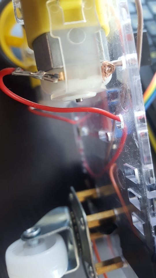
Connect Motor Wires: Attach a wire to each terminal of the motors. Soldering is ideal for a robust connection, but if you don’t have a soldering iron, you can carefully twist the wires around the motor pins to ensure contact.
-
Prepare USB Cable for Power: Take an old USB cable and cut off one end, leaving about 20cm (8 inches) of cable.
-
Expose Power Wires: Carefully strip a few centimeters of the outer insulation to reveal the wires inside. You’ll typically find 4 or 5 wires, but we’re interested in the red (positive, +) and black (ground, GND) wires. Strip about 2-4 cm of insulation from these two wires. For a more secure connection, you can twist or solder these to longer, stronger wires or jumper wires.
Alt text: Stripped USB cable showing red and black wires for power connection in the DIY remote control car guide.
-
Mount Motors to Chassis: Attach the motors to the chassis frame using the plastic brackets, screws, and nuts. Most motors have a small dot on one side; ensure these dots face inwards towards each other when both motors are mounted.
-
Install Supporting Wheel: Locate the four small holes in a square pattern at the end of the chassis frame. Use brass spacers and screws to mount them in these holes, ensuring the spacers are on the same side of the frame as the motors.
-
Attach Nylon Wheel: Mount the nylon supporting wheel to the brass spacers using screws. This wheel provides stability to the car.
-
Mount Drive Wheels: Push the drive wheels onto the motor shafts. There’s a specific shape inside the wheel hub that needs to align with the motor shaft. It might require a bit of force, but be gentle and ensure they are securely attached.
-
Mount Electronic Boards: Now, you can mount the Arduino UNO board and the DC motor controller onto the chassis frame. Use screws and nuts left over from the kit. Insulate any exposed wires with electrical tape to prevent shorts.
Step 2: Wiring the Electronic Components
With the chassis assembled and the boards mounted, it’s time to connect everything together. Prepare your male-male and female-male jumper wires.
-
Connect Motors to Motor Controller: Connect the wires from the motors to the DC motor controller’s output terminals (OUT1, OUT2, OUT3, OUT4). Typically, the lower pins (closer to the edge of the board) are positive (+), and the upper pins are ground (GND, -). Follow this wiring scheme:
- OUT1: Left motor (-) GND wire
- OUT2: Left motor (+) wire
- OUT3: Right motor (+) wire
- OUT4: Right motor (-) GND wire
-
Connect Arduino to Motor Controller: Use jumper wires to connect the Arduino to the motor controller’s input pins (IN1, IN2, IN3, IN4). These pins will receive control signals from the Arduino to drive the motors. Female-male jumpers are usually needed.
- IN1: Arduino Digital Pin 5
- IN2: Arduino Digital Pin 6
- IN3: Arduino Digital Pin 10
- IN4: Arduino Digital Pin 11
-
Connect Bluetooth Module: The Bluetooth module (HC-06 or HC-05) enables wireless control of the car. It typically has 4 pins: VCC (Power), GND (Ground), TXD (Transmit Data), and RXD (Receive Data). Use female-male jumpers to connect it as follows:
- VCC: Arduino 5V pin
- GND: Arduino GND pin
- TXD: Arduino Digital Pin 0 (RXD) – Note the cross-connection: TX to RX
- RXD: Arduino Digital Pin 1 (TXD) – Note the cross-connection: RX to TX
Data is exchanged between the Arduino and the Bluetooth module, hence the cross-wiring of TX and RX pins.
-
Connect Piezo Buzzer (Optional): A piezo buzzer adds sound effects to your RC car. It has two legs: a longer leg (Anode, +) and a shorter leg (Cathode, -). While a 330 Ohm resistor is recommended for sensitive buzzers, it can sometimes make the sound very faint. For this project, we’ll connect it directly:
- Anode (+, longer leg): Arduino Digital Pin 3
- Cathode (-, shorter leg): Arduino GND pin
-
Powering the Motor Controller: Use the USB cable you prepared earlier. Connect the red wire (+) to the 12V input on the motor controller and the black wire (-) to the GND next to it.
-
Powering the Circuit: Connect two USB cables to your power bank. One cable powers the Arduino board (plug into the Arduino’s USB port), and the other powers the DC motor controller (plug the USB connector of the prepared USB cable into the power bank). Mount the power bank onto the chassis using electrical tape or another mounting method. Some power banks have a power button, so ensure it’s switched on to supply power.
With all the components wired, we’re ready to program the Arduino and control our RC car!
Step 3: Programming the Arduino and Mobile App
Now for the exciting part – bringing your RC car to life with code!
-
Install Arduino IDE: If you haven’t already, download and install the Arduino IDE (Integrated Development Environment) from the official Arduino website (https://www.arduino.cc/).
-
Configure Arduino IDE: Open the Arduino IDE. Go to “Tools” > “Board:” and select “Arduino Uno” (or your specific Arduino board). Then, go to “Tools” > “Port:” and choose the port that your Arduino is connected to. The port will usually appear after you connect your Arduino to your computer via USB. If it’s greyed out, try different USB ports on your computer.
-
Upload the Code: You have two options for uploading the code:
a. Download and Open: Download the provided Arduino code file (if available as a separate file). Open it directly in the Arduino IDE.
b. Copy and Paste: Copy the code provided below. In the Arduino IDE, create a new sketch (File > New) and paste the code into the editor window.#define in1 5 #define in2 6 #define in3 10 #define in4 11 int state; int piezo = 3; void setup() { pinMode(in1, OUTPUT); pinMode(in2, OUTPUT); pinMode(in3, OUTPUT); pinMode(in4, OUTPUT); pinMode(piezo,OUTPUT); Serial.begin(9600); } void loop() { if (Serial.available() > 0) { state = Serial.read(); Stop(); switch (state) { case 'F': forward(); soundFX(3000.0,30+400*(1+sin(millis()/5000))); break; case 'G': forwardleft(); soundFX(3000.0,60); break; case 'D': forwardright(); soundFX(3000.0,60); break; case 'N': backright(); soundFX(3000.0,30+100*(1+sin(millis()/2500))); break; case 'C': backleft(); soundFX(3000.0,30+100*(1+sin(millis()/2500))); soundFX(3000.0,30+100*(1+sin(millis()/2500))); soundFX(3000.0,30+100*(1+sin(millis()/2500))); soundFX(3000.0,30+100*(1+sin(millis()/2500))); break; case 'B': back(); soundFX(3000.0,30+200*(1+sin(millis()/2500))); soundFX(3000.0,30+200*(1+sin(millis()/2500))); soundFX(3000.0,30+200*(1+sin(millis()/2500))); soundFX(3000.0,30+200*(1+sin(millis()/2500))); break; case 'L': left(); soundFX(3000.0,60); soundFX(3000.0,60); soundFX(3000.0,60); soundFX(3000.0,60); break; case 'R': right(); soundFX(3000.0,60); soundFX(3000.0,60); soundFX(3000.0,60); soundFX(3000.0,60); break; case 'H': soundFX(3000.0,30+200*(1+sin(millis()/2500))); soundFX(3000.0,60); soundFX(3000.0,30+200*(1+sin(millis()/2500))); soundFX(3000.0,60); } } } void forward() { analogWrite(in1, 255); analogWrite(in3, 255); } void forwardleft() { analogWrite(in1, 50); analogWrite(in3, 255); } void forwardright() { analogWrite(in1, 255); analogWrite(in3, 50); } void back() { analogWrite(in2, 255); analogWrite(in4, 255); } void backright() { analogWrite(in2, 50); analogWrite(in4, 255); } void backleft() { analogWrite(in2, 255); analogWrite(in4, 50); } void left() { analogWrite(in4, 255); analogWrite(in1, 255); } void right() { analogWrite(in3, 255); analogWrite(in2, 255); } void Stop() { analogWrite(in1, 0); analogWrite(in2, 0); analogWrite(in3, 0); analogWrite(in4, 0); } void soundFX(float amplitude,float period){ int uDelay=2+amplitude+amplitude*sin(millis()/period); for(int i=0;i<amplitude;i++) { digitalWrite(piezo, HIGH); delayMicroseconds(uDelay); digitalWrite(piezo, LOW); delayMicroseconds(uDelay); } }Important Note: Disconnect the Bluetooth module’s RX (Digital 0) and TX (Digital 1) pins from the Arduino before uploading the code. These pins are used for serial communication with your computer during the upload process, and interference from the Bluetooth module can cause upload failures.
Click the “Upload” button (the right arrow icon) in the Arduino IDE to compile and upload the code to your Arduino board.
-
Reconnect Bluetooth Module: Once the code is uploaded, reconnect the Bluetooth module’s RX and TX pins to the Arduino. Also, reconnect the USB cable from the Arduino to the power bank.
-
Install and Use the Android App: Download the “ArduCar – Arduino RC Car Bluetooth Controller” app from the Google Play Store: .
Launch the app on your Android phone and follow the app’s instructions to connect to your RC car via Bluetooth. You can now control your car using the on-screen controls in the app!
Congratulations! You’ve successfully built and programmed your own Arduino-controlled RC car.
Step 4: Understanding the Arduino Code and Bluetooth Configuration (Optional)
For those interested in delving deeper into the code and potentially customizing their RC car further, here’s a breakdown of the Arduino code and some notes on Bluetooth configuration.
Arduino Code Explanation
The Arduino code is written in a simplified version of C/C++. Let’s break it down section by section:
1. Variable and Pin Definitions:
#define in1 5
#define in2 6
#define in3 10
#define in4 11
int state;
int piezo = 3;
#define in1 5: This line assigns the namein1to Arduino Digital Pin 5. We do this for each motor control pin (in1 to in4) connected to the L298N motor controller. This makes the code more readable as we can refer toin1instead of remembering pin number 5.int state;: Declares an integer variable namedstate. This variable will store the commands received from the Bluetooth module.int piezo = 3;: Assigns the namepiezoto Arduino Digital Pin 3, which is connected to the piezo buzzer.
2. void setup() { } Function:
void setup() {
  pinMode(in1, OUTPUT);
  pinMode(in2, OUTPUT);
  pinMode(in3, OUTPUT);
  pinMode(in4, OUTPUT);
  pinMode(piezo,OUTPUT);
  Serial.begin(9600);
}- The
setup()function runs once at the beginning of the program. pinMode(in1, OUTPUT);: Configures Digital Pin 5 (and pins 6, 10, 11, and 3) as OUTPUT pins. This means the Arduino will send signals out from these pins to control the motor controller and buzzer.Serial.begin(9600);: Initializes serial communication at a baud rate of 9600 bits per second. This is the communication channel used to receive data from the Bluetooth module. 9600 is a common and stable baud rate for Bluetooth communication.
3. void loop() { } Function:
void loop() {
  if (Serial.available() > 0) {
    state = Serial.read();
    Stop();
    switch (state) {
      // ... (cases for different commands) ...
    }
  }
}- The
loop()function runs continuously aftersetup()finishes. if (Serial.available() > 0): Checks if there is any data available to be read from the serial port (i.e., from the Bluetooth module).state = Serial.read();: If data is available, it reads the first byte of data received and stores it in thestatevariable. This byte represents the command sent from the Android app (like ‘F’ for forward, ‘L’ for left, etc.).Stop();: Calls theStop()function (explained later) to immediately stop the car before executing a new command. This ensures smooth transitions between commands.switch (state) { ... }: Aswitchstatement checks the value of thestatevariable and executes different code blocks based on the received command character.case 'F': forward(); soundFX(...); break;: Ifstateis ‘F’, it calls theforward()function to move the car forward and also plays a sound effect usingsoundFX(). Eachcasecorresponds to a different command character sent from the app (Forward, Backward, Left, Right, etc.). Thebreak;statement exits theswitchblock after executing the corresponding case.
4. Movement Functions (forward(), back(), left(), right(), Stop()):
These functions control the motors via the L298N motor controller. Let’s look at forward() as an example:
void forward() {
  analogWrite(in1, 255);
  analogWrite(in3, 255);
}
void forward() { ... }: Defines a function namedforward()that takes no arguments and returns nothing (void).analogWrite(in1, 255);: Sends a PWM (Pulse Width Modulation) signal with a value of 255 to thein1pin (Arduino Digital Pin 5).analogWrite()is used to control the speed of the motors. A value of 255 represents full speed, and 0 represents no speed. By settingin1andin3to 255 and controllingin2andin4accordingly in other functions, we control the direction and speed of each motor, thus controlling the car’s movement.analogWrite(in3, 255);: Sends a PWM signal to thein3pin (Arduino Digital Pin 10) to control the other motor.
The other movement functions (back(), left(), right(), forwardleft(), forwardright(), backleft(), backright()) work similarly, by sending different PWM signals to the motor control pins to achieve the desired movement. The Stop() function sets all motor control pins to 0, effectively stopping both motors.
5. soundFX() Function:
void soundFX(float amplitude,float period){
  int uDelay=2+amplitude+amplitude*sin(millis()/period);
  for(int i=0;i<amplitude;i++) {
    digitalWrite(piezo, HIGH);
    delayMicroseconds(uDelay);
    digitalWrite(piezo, LOW);
    delayMicroseconds(uDelay);
  }
}
void soundFX(float amplitude, float period) { ... }: Defines a function namedsoundFX()that takes two floating-point arguments,amplitudeandperiod, to control the sound produced by the piezo buzzer. This code is inspired by sound synthesis examples for Arduino and creates a simple tone. You can explore and modify this function to create different sound effects.
Bluetooth Configuration (Optional)
HC-05 and HC-06 Bluetooth modules typically come with default settings (like baud rate, name, and password). For basic use, the default settings usually work fine. However, if you want to customize your Bluetooth module (e.g., change the name it broadcasts or set a password), you can configure it using AT commands via the Arduino IDE serial monitor.
Important Considerations for Bluetooth Configuration:
- Voltage Levels: Bluetooth modules often operate at 3.3V logic levels, while Arduino UNO outputs 5V. For reliable communication and to avoid damaging the Bluetooth module, it’s recommended to use voltage dividers on the Arduino TX pin (connected to Bluetooth RX) to reduce the voltage to 3.3V. However, for basic projects and short-distance communication, direct connection might work, but proceed with caution and research voltage level compatibility for your specific modules.
- Configuration Mode: To configure the Bluetooth module, you usually need to put it into “AT command mode.” The method to enter AT command mode varies depending on the module (HC-05 vs. HC-06 and specific versions). Consult the datasheet or tutorials specific to your Bluetooth module for instructions on entering AT command mode.
- Serial Monitor: You’ll use the Arduino IDE’s Serial Monitor to send AT commands and receive responses from the Bluetooth module. Set the baud rate in the Serial Monitor to match the AT command baud rate of your Bluetooth module (often 38400 or 9600, check your module’s documentation).
Example AT Commands (Refer to your module’s documentation for the correct commands):
AT: Test command (should respond with “OK”)AT+NAME=MyRCar: Set Bluetooth name to “MyRCar”AT+PIN=1234: Set PIN code to “1234”AT+BAUD=9600: Set baud rate to 9600
There are numerous online tutorials and resources that provide detailed instructions on configuring HC-05 and HC-06 Bluetooth modules using AT commands. Search for “HC-05 AT commands” or “HC-06 AT commands” to find step-by-step guides if you wish to explore Bluetooth configuration further.
We hope you enjoyed building and programming your Arduino RC car! This project is a stepping stone to more complex robotics and electronics adventures. Feel free to experiment, modify the code, add more features, and share your creations! If you have any questions or suggestions, please leave them in the comments below. Happy making!